Garrattfan's Modelrailroading Pages

LTM 51 in HO
Detailing of the drive units
- Introduction
- History of the LTM 51
- Inventory of the kit
- Instruction manual
- A preview
- Project preparations
- Boiler cradle - Main construction
- Pivots
- Boiler
- Drive units - Chassis
- Sprung frames
- Gearbox and motor
- Coupling rods
- Drive units - Superstructure
- First assembly and trial run
- Drive units - Detailing
- Boiler cradle - Detailing

In het Nederlands
In March 2021 I was caught running around in circles at the start of the detailing of the boiler cradle. I kept staring at photos, where which tube would go along the boiler. And every time I picked up the model to do the first details I got in doubt again, put the model down and achieved nothing once more. To break this stalemate I turned my head to completing the drive units. There the situation was much clearer. Brace yourself, this is going to be a long read. Not only were there many details to add, there was also much work in each detail as I needed to make many parts myself |
|||||||||||||||||||||||||||||||||||||||||||||||||||||||||||||||||||||||||||||||||||||||||||||||||||||||||||||||||||||||||||||||||||||||||||||
|
|||||||||||||||||||||||||||||||||||||||||||||||||||||||||||||||||||||||||||||||||||||||||||||||||||||||||||||||||||||||||||||||||||||||||||||
IndexEven so I had make a substantial to do list. It was quite a lot more work than I originally thought. For the oversight of the is page I mad an index on which I recorded the progress.
|
|||||||||||||||||||||||||||||||||||||||||||||||||||||||||||||||||||||||||||||||||||||||||||||||||||||||||||||||||||||||||||||||||||||||||||||
Prepping the engine cover |
|||||||||||||||||||||||||||||||||||||||||||||||||||||||||||||||||||||||||||||||||||||||||||||||||||||||||||||||||||||||||||||||||||||||||||||
| Detailing work started with filling the gaps that where visible on the top edges of the engine cover. In the original etch there were slots etched and I partially filled them up with solder but did not manage to get rid of them entirely. | |||||||||||||||||||||||||||||||||||||||||||||||||||||||||||||||||||||||||||||||||||||||||||||||||||||||||||||||||||||||||||||||||||||||||||||
 |
 |
||||||||||||||||||||||||||||||||||||||||||||||||||||||||||||||||||||||||||||||||||||||||||||||||||||||||||||||||||||||||||||||||||||||||||||
The engine cover as I found it on the etch The black lines clearly signals the etched through surface. |
Even when filled the seam is still visible |
||||||||||||||||||||||||||||||||||||||||||||||||||||||||||||||||||||||||||||||||||||||||||||||||||||||||||||||||||||||||||||||||||||||||||||
 I filled them with JB Weld. |
|||||||||||||||||||||||||||||||||||||||||||||||||||||||||||||||||||||||||||||||||||||||||||||||||||||||||||||||||||||||||||||||||||||||||||||
 |
 |
||||||||||||||||||||||||||||||||||||||||||||||||||||||||||||||||||||||||||||||||||||||||||||||||||||||||||||||||||||||||||||||||||||||||||||
The etched recesses at the back of the engine cover (left) were also filled. This side was etched as if it had hinging doors like the front side but on close inspection no doors could have existed at that location, just plain metal sheet. After sanding I gave the superstructure a quick primer to reveal the spots I had missed during filling and filing. After a few minor adjustments I was happy and removed the primer again. |
|||||||||||||||||||||||||||||||||||||||||||||||||||||||||||||||||||||||||||||||||||||||||||||||||||||||||||||||||||||||||||||||||||||||||||||
| Return to index | |||||||||||||||||||||||||||||||||||||||||||||||||||||||||||||||||||||||||||||||||||||||||||||||||||||||||||||||||||||||||||||||||||||||||||||
Steam pipes |
|||||||||||||||||||||||||||||||||||||||||||||||||||||||||||||||||||||||||||||||||||||||||||||||||||||||||||||||||||||||||||||||||||||||||||||
I was now supposed to drill two holes in the back of the engine cover to allow two steam pipes to go through and somehow mount these pipes. After careful consideration I decided not to. It is fiddly to drill them at all and the steam pipes may conflict with the free movement of the drive unit relative to the running board of the boiler cradle.
Once painted it will be a very dark spot and the absence of these pipe is not immediately apparent. You have to draw a line somewhere in what you can do in 1:87 |
 |
||||||||||||||||||||||||||||||||||||||||||||||||||||||||||||||||||||||||||||||||||||||||||||||||||||||||||||||||||||||||||||||||||||||||||||
| Return to index | |||||||||||||||||||||||||||||||||||||||||||||||||||||||||||||||||||||||||||||||||||||||||||||||||||||||||||||||||||||||||||||||||||||||||||||
Equaliser tube |
|||||||||||||||||||||||||||||||||||||||||||||||||||||||||||||||||||||||||||||||||||||||||||||||||||||||||||||||||||||||||||||||||||||||||||||
The equaliser tube does exactly what the name suggests: it equalises the water levels between the left and righthand water tanks. It is slung under the the frames and the two water tanks in a stretched U-form.
It is not possible to model the entire pipe. The horizontal tube would interfere with the frames during assembly. I decided to model the elbows and a stub of the horizontal part, leaving the frames free to pass. It makes the fabrication easier as well. It is no longer necessary to aim for a specific width of the horizontal tube. It also makes bending the elbow easier as you will see. |
 |
||||||||||||||||||||||||||||||||||||||||||||||||||||||||||||||||||||||||||||||||||||||||||||||||||||||||||||||||||||||||||||||||||||||||||||
 |
First I turned the elbow-to-be from 3.0 mm brass rod, leaving two flanges proud of the surface.
|
||||||||||||||||||||||||||||||||||||||||||||||||||||||||||||||||||||||||||||||||||||||||||||||||||||||||||||||||||||||||||||||||||||||||||||
The tubes are very wide and bending a 90 degree corner in 2.2 mm thick brass rod is no easy feat. So after turning I annealed the brass rod. I made myself two bending handles from steel in which I drilled a 2.2 mm hole. |
|||||||||||||||||||||||||||||||||||||||||||||||||||||||||||||||||||||||||||||||||||||||||||||||||||||||||||||||||||||||||||||||||||||||||||||
 |
 |
||||||||||||||||||||||||||||||||||||||||||||||||||||||||||||||||||||||||||||||||||||||||||||||||||||||||||||||||||||||||||||||||||||||||||||
With the handles the bending operation becomes relatively easy. By gently bending the elbow a bit over 90 degrees and then ease it back with a bit of luck the flanges stand at 90 degrees. It is a bit of trial and error. I chamfered the ends on handles after bending the first elbow to make the bending "over 90 degrees" easier |
|||||||||||||||||||||||||||||||||||||||||||||||||||||||||||||||||||||||||||||||||||||||||||||||||||||||||||||||||||||||||||||||||||||||||||||
 |
|||||||||||||||||||||||||||||||||||||||||||||||||||||||||||||||||||||||||||||||||||||||||||||||||||||||||||||||||||||||||||||||||||||||||||||
 |
 |
||||||||||||||||||||||||||||||||||||||||||||||||||||||||||||||||||||||||||||||||||||||||||||||||||||||||||||||||||||||||||||||||||||||||||||
| The final result | |||||||||||||||||||||||||||||||||||||||||||||||||||||||||||||||||||||||||||||||||||||||||||||||||||||||||||||||||||||||||||||||||||||||||||||
| Return to index | |||||||||||||||||||||||||||||||||||||||||||||||||||||||||||||||||||||||||||||||||||||||||||||||||||||||||||||||||||||||||||||||||||||||||||||
Lubricators |
|||||||||||||||||||||||||||||||||||||||||||||||||||||||||||||||||||||||||||||||||||||||||||||||||||||||||||||||||||||||||||||||||||||||||||||
| At the front of the engine cover there are sets of three lubricators. Well actually two and a kind of junction in the lubricator pipes. I decided to mimic them as three lubricators. I am now at the edge of what I can still do. In fact before I started I was more or less convinced I was over that edge: simply too tiny. But I did not want to leave these details away without trying. So I tried. Judge the result yourself. | |||||||||||||||||||||||||||||||||||||||||||||||||||||||||||||||||||||||||||||||||||||||||||||||||||||||||||||||||||||||||||||||||||||||||||||
|
|
||||||||||||||||||||||||||||||||||||||||||||||||||||||||||||||||||||||||||||||||||||||||||||||||||||||||||||||||||||||||||||||||||||||||||||
| The lubricators are mounted on a bracket. First I milled an L-profile from a piece of rail profile that I soldered to a sacrificial piece of brass. Legs 1.3 mm by 1.3 mm and 0.2 mm thick! After milling I drilled the holes on their appropriate places and cut the profile in lengths of 5 mm. | |||||||||||||||||||||||||||||||||||||||||||||||||||||||||||||||||||||||||||||||||||||||||||||||||||||||||||||||||||||||||||||||||||||||||||||
|
|||||||||||||||||||||||||||||||||||||||||||||||||||||||||||||||||||||||||||||||||||||||||||||||||||||||||||||||||||||||||||||||||||||||||||||
 |
 |
||||||||||||||||||||||||||||||||||||||||||||||||||||||||||||||||||||||||||||||||||||||||||||||||||||||||||||||||||||||||||||||||||||||||||||
I turned the lubricators from 1.2 mm brass rod. Dimension: 1.2 mm high, 0.8 mm wide and the stem is 0.5 mm wide. |
|||||||||||||||||||||||||||||||||||||||||||||||||||||||||||||||||||||||||||||||||||||||||||||||||||||||||||||||||||||||||||||||||||||||||||||
 |
 |
||||||||||||||||||||||||||||||||||||||||||||||||||||||||||||||||||||||||||||||||||||||||||||||||||||||||||||||||||||||||||||||||||||||||||||
| They were soldered on the brackets in trios. | |||||||||||||||||||||||||||||||||||||||||||||||||||||||||||||||||||||||||||||||||||||||||||||||||||||||||||||||||||||||||||||||||||||||||||||
|
|||||||||||||||||||||||||||||||||||||||||||||||||||||||||||||||||||||||||||||||||||||||||||||||||||||||||||||||||||||||||||||||||||||||||||||
| Return to index | |||||||||||||||||||||||||||||||||||||||||||||||||||||||||||||||||||||||||||||||||||||||||||||||||||||||||||||||||||||||||||||||||||||||||||||
Handgrips of the hatches |
|||||||||||||||||||||||||||||||||||||||||||||||||||||||||||||||||||||||||||||||||||||||||||||||||||||||||||||||||||||||||||||||||||||||||||||
 |
 |
||||||||||||||||||||||||||||||||||||||||||||||||||||||||||||||||||||||||||||||||||||||||||||||||||||||||||||||||||||||||||||||||||||||||||||
| Making the handgrips on the hatch covers is a simple job but requires a good amount of patience. Here repeatability is of the utmost importance. When four identical parts are not identical it immediately attracts attention. After soldering the excess material on the inside of the superstructure is cut short and filed flush | |||||||||||||||||||||||||||||||||||||||||||||||||||||||||||||||||||||||||||||||||||||||||||||||||||||||||||||||||||||||||||||||||||||||||||||
|
|||||||||||||||||||||||||||||||||||||||||||||||||||||||||||||||||||||||||||||||||||||||||||||||||||||||||||||||||||||||||||||||||||||||||||||
| After having bent eight handgrips by hand, I got fed up with tiresome work of getting them all exactly in the right shape, which more or less a hit and miss affair. So I decided to make a forming tool: a U-shaped slot into which the wire was pressed in the right form. | |||||||||||||||||||||||||||||||||||||||||||||||||||||||||||||||||||||||||||||||||||||||||||||||||||||||||||||||||||||||||||||||||||||||||||||
 |
The slot should be as wide a the outside size of the grips which is 1.76 mm. I do not have the tool to measure an inside size this small. So I first made a positive of 1.73 mm wide. | ||||||||||||||||||||||||||||||||||||||||||||||||||||||||||||||||||||||||||||||||||||||||||||||||||||||||||||||||||||||||||||||||||||||||||||
|
 |
||||||||||||||||||||||||||||||||||||||||||||||||||||||||||||||||||||||||||||||||||||||||||||||||||||||||||||||||||||||||||||||||||||||||||||
| Then I filed a negative slot in which this positive would just fit in. So the theory is now that this slot is just a few hundreds over 1.73. | |||||||||||||||||||||||||||||||||||||||||||||||||||||||||||||||||||||||||||||||||||||||||||||||||||||||||||||||||||||||||||||||||||||||||||||
|
 Take a piece of steel 1.2 mm wide (that the width of the U minus twice the wire thickness of 0.3 mm). Take a piece of steel 1.2 mm wide (that the width of the U minus twice the wire thickness of 0.3 mm). |
||||||||||||||||||||||||||||||||||||||||||||||||||||||||||||||||||||||||||||||||||||||||||||||||||||||||||||||||||||||||||||||||||||||||||||
|
|
||||||||||||||||||||||||||||||||||||||||||||||||||||||||||||||||||||||||||||||||||||||||||||||||||||||||||||||||||||||||||||||||||||||||||||
|
 And five minutes later I have eight identical grips. And five minutes later I have eight identical grips. |
||||||||||||||||||||||||||||||||||||||||||||||||||||||||||||||||||||||||||||||||||||||||||||||||||||||||||||||||||||||||||||||||||||||||||||
 |
 |
||||||||||||||||||||||||||||||||||||||||||||||||||||||||||||||||||||||||||||||||||||||||||||||||||||||||||||||||||||||||||||||||||||||||||||
| Although I did succeed getting the first eight grips on one unit into place pretty well I struggled to do the other unit. So I made myself a small tool: a piece of aluminium with a lip at the bottom. The is 0.6 mm wide, the depth for which the grip should protrude form the hatch's surface and 0.2 mm high to clear the grip from the running board. It worked well, though it still was not easy. I am still wondering why I could install the first eight grips within half an hour and struggled for another day to get the other eight done. Very frustrating. | |||||||||||||||||||||||||||||||||||||||||||||||||||||||||||||||||||||||||||||||||||||||||||||||||||||||||||||||||||||||||||||||||||||||||||||
| Return to index | |||||||||||||||||||||||||||||||||||||||||||||||||||||||||||||||||||||||||||||||||||||||||||||||||||||||||||||||||||||||||||||||||||||||||||||
Lubricator pumps |
|||||||||||||||||||||||||||||||||||||||||||||||||||||||||||||||||||||||||||||||||||||||||||||||||||||||||||||||||||||||||||||||||||||||||||||
 |
The lubricator is a tiny thing, the height being just 4.2 mm and the diameter at the rings 2.3 mm. Yet I managed to turn a decent representation from 3 mm brass rod. I drilled the body to 0.7 mm followed by a 1.2 mm drill and the the forward facing parts and soldered (240 C) it in place. The small seam on the right hand photo below is only visible on the photo. |
||||||||||||||||||||||||||||||||||||||||||||||||||||||||||||||||||||||||||||||||||||||||||||||||||||||||||||||||||||||||||||||||||||||||||||
 |
 |
||||||||||||||||||||||||||||||||||||||||||||||||||||||||||||||||||||||||||||||||||||||||||||||||||||||||||||||||||||||||||||||||||||||||||||
 |
|||||||||||||||||||||||||||||||||||||||||||||||||||||||||||||||||||||||||||||||||||||||||||||||||||||||||||||||||||||||||||||||||||||||||||||
| Return to index | |||||||||||||||||||||||||||||||||||||||||||||||||||||||||||||||||||||||||||||||||||||||||||||||||||||||||||||||||||||||||||||||||||||||||||||
Tube from the lubricator pump |
|||||||||||||||||||||||||||||||||||||||||||||||||||||||||||||||||||||||||||||||||||||||||||||||||||||||||||||||||||||||||||||||||||||||||||||
The place tends to accumulate dirt of all kinds. I will clean that out later.
|
|||||||||||||||||||||||||||||||||||||||||||||||||||||||||||||||||||||||||||||||||||||||||||||||||||||||||||||||||||||||||||||||||||||||||||||
| Return to index | |||||||||||||||||||||||||||||||||||||||||||||||||||||||||||||||||||||||||||||||||||||||||||||||||||||||||||||||||||||||||||||||||||||||||||||
Sandbox covers |
|||||||||||||||||||||||||||||||||||||||||||||||||||||||||||||||||||||||||||||||||||||||||||||||||||||||||||||||||||||||||||||||||||||||||||||
| There are two somewhat nondescript rectangles on the front of the running board on either side of the engine cover. These turned out to be the access hatches to the sandboxes that are located on front of the leading axle. | |||||||||||||||||||||||||||||||||||||||||||||||||||||||||||||||||||||||||||||||||||||||||||||||||||||||||||||||||||||||||||||||||||||||||||||
 |
 |
||||||||||||||||||||||||||||||||||||||||||||||||||||||||||||||||||||||||||||||||||||||||||||||||||||||||||||||||||||||||||||||||||||||||||||
 |
Construction is simple. Rectangles are cut from brass strip.
The difference in size creates an overhang of 0.15 mm to all sides. It all sounds easy but getting a small part like this perfectly square and true and accurately to size is a work of filing with great care and patience. I laminated the two layers together with 240 C solder. |
||||||||||||||||||||||||||||||||||||||||||||||||||||||||||||||||||||||||||||||||||||||||||||||||||||||||||||||||||||||||||||||||||||||||||||
 |
Four of them, the left correctly positioned, the two on the right upside down to show the 0.15 mm overhang. | ||||||||||||||||||||||||||||||||||||||||||||||||||||||||||||||||||||||||||||||||||||||||||||||||||||||||||||||||||||||||||||||||||||||||||||
 |
All four were sweated in place with 140C solder | ||||||||||||||||||||||||||||||||||||||||||||||||||||||||||||||||||||||||||||||||||||||||||||||||||||||||||||||||||||||||||||||||||||||||||||
| Return to index | |||||||||||||||||||||||||||||||||||||||||||||||||||||||||||||||||||||||||||||||||||||||||||||||||||||||||||||||||||||||||||||||||||||||||||||
Watertank hatches |
|||||||||||||||||||||||||||||||||||||||||||||||||||||||||||||||||||||||||||||||||||||||||||||||||||||||||||||||||||||||||||||||||||||||||||||
 |
The hatches as provided in the etches were not to my liking. They needed all round cleaning up of the etch cusps, a job I was hardly looking forward to, and then soldering together before accurate positioning on the running board without a clear centre point. And even then I would be stuck with hatches that showed a small recess instead of the bulbous raised centre of the original. | ||||||||||||||||||||||||||||||||||||||||||||||||||||||||||||||||||||||||||||||||||||||||||||||||||||||||||||||||||||||||||||||||||||||||||||
 |
So before going in to that I decided to have a go at making these hatches myself on the lathe. And my word, they came out pretty easily! | ||||||||||||||||||||||||||||||||||||||||||||||||||||||||||||||||||||||||||||||||||||||||||||||||||||||||||||||||||||||||||||||||||||||||||||
 |
I miscalculated the height (left) but on a second attempt (right) a hatch emerged that was hardly any higher than the sandbox covers, 0.7 mm total height!. With the locating pin of 1.0 mm it should be possible to locate the hatch accurately on the running board. and solder it from the inside. | ||||||||||||||||||||||||||||||||||||||||||||||||||||||||||||||||||||||||||||||||||||||||||||||||||||||||||||||||||||||||||||||||||||||||||||
I drilled out the holes and soldered the hatches from the inside. The spigots made for easy positioning and soldering. |
|||||||||||||||||||||||||||||||||||||||||||||||||||||||||||||||||||||||||||||||||||||||||||||||||||||||||||||||||||||||||||||||||||||||||||||
| Return to index | |||||||||||||||||||||||||||||||||||||||||||||||||||||||||||||||||||||||||||||||||||||||||||||||||||||||||||||||||||||||||||||||||||||||||||||
Profile on the skirt below the buffer beam |
|||||||||||||||||||||||||||||||||||||||||||||||||||||||||||||||||||||||||||||||||||||||||||||||||||||||||||||||||||||||||||||||||||||||||||||
 |
Immediately at delivery the LTM 51 had a rim at the lower end of the skirt. It also sported two curious looking brooms as rail cleaners. These are only visible on builder's photos so presumable they did not work as intended and where quickly removed after entering service. After about two years an extra profile was added at the lower end of the skirt. I don't have the faintest idea what it's function was. I decided the model the LTM 51 in this condition. | ||||||||||||||||||||||||||||||||||||||||||||||||||||||||||||||||||||||||||||||||||||||||||||||||||||||||||||||||||||||||||||||||||||||||||||
 |
First soldered a T-profile to a sacrificial brass plate and milled it in half, leaving just 0.2 mm on the vertical part. | ||||||||||||||||||||||||||||||||||||||||||||||||||||||||||||||||||||||||||||||||||||||||||||||||||||||||||||||||||||||||||||||||||||||||||||
|
I made two small pieces of brass strip and soldered (240C) them in the angle of the profile | ||||||||||||||||||||||||||||||||||||||||||||||||||||||||||||||||||||||||||||||||||||||||||||||||||||||||||||||||||||||||||||||||||||||||||||
and then soldered the profiles on the skirts. |
|||||||||||||||||||||||||||||||||||||||||||||||||||||||||||||||||||||||||||||||||||||||||||||||||||||||||||||||||||||||||||||||||||||||||||||
A close up, showing that there is a neat gap between the profile and the skirt |
|||||||||||||||||||||||||||||||||||||||||||||||||||||||||||||||||||||||||||||||||||||||||||||||||||||||||||||||||||||||||||||||||||||||||||||
| Return to index | |||||||||||||||||||||||||||||||||||||||||||||||||||||||||||||||||||||||||||||||||||||||||||||||||||||||||||||||||||||||||||||||||||||||||||||
Handgrips below the buffers |
|||||||||||||||||||||||||||||||||||||||||||||||||||||||||||||||||||||||||||||||||||||||||||||||||||||||||||||||||||||||||||||||||||||||||||||
 |
I first marked the line where to drill and punched a dent and then carefully drilled four 0.3 mm holes. Note that the etch provided holes on either side of the buffers in the front of the buffer beam. BUT the photos clearly demonstrate the grips come from under the beam and are not symmetrically located around the buffers. Hence I made my own holes. | ||||||||||||||||||||||||||||||||||||||||||||||||||||||||||||||||||||||||||||||||||||||||||||||||||||||||||||||||||||||||||||||||||||||||||||
|
Similar to the grips on the engine covers, I made a small fixture to hold the handgrip in position for soldering. | ||||||||||||||||||||||||||||||||||||||||||||||||||||||||||||||||||||||||||||||||||||||||||||||||||||||||||||||||||||||||||||||||||||||||||||
|
|||||||||||||||||||||||||||||||||||||||||||||||||||||||||||||||||||||||||||||||||||||||||||||||||||||||||||||||||||||||||||||||||||||||||||||
| Return to index | |||||||||||||||||||||||||||||||||||||||||||||||||||||||||||||||||||||||||||||||||||||||||||||||||||||||||||||||||||||||||||||||||||||||||||||
At the step in side of the water tank |
|||||||||||||||||||||||||||||||||||||||||||||||||||||||||||||||||||||||||||||||||||||||||||||||||||||||||||||||||||||||||||||||||||||||||||||
 |
 |
||||||||||||||||||||||||||||||||||||||||||||||||||||||||||||||||||||||||||||||||||||||||||||||||||||||||||||||||||||||||||||||||||||||||||||
| Same story for the tiny handgrips at the steps. A very small fixture was made for this one: 1.5 mm wide and a mere 0.6 thick. | |||||||||||||||||||||||||||||||||||||||||||||||||||||||||||||||||||||||||||||||||||||||||||||||||||||||||||||||||||||||||||||||||||||||||||||
|
|||||||||||||||||||||||||||||||||||||||||||||||||||||||||||||||||||||||||||||||||||||||||||||||||||||||||||||||||||||||||||||||||||||||||||||
| Return to index | |||||||||||||||||||||||||||||||||||||||||||||||||||||||||||||||||||||||||||||||||||||||||||||||||||||||||||||||||||||||||||||||||||||||||||||
Headlamps |
|||||||||||||||||||||||||||||||||||||||||||||||||||||||||||||||||||||||||||||||||||||||||||||||||||||||||||||||||||||||||||||||||||||||||||||
| The headlamps caused me a headache. Previous builds had shown me they are incredibly difficult to position correctly. First, they have no less than five dimensions of freedom, as shown in the pictures below. | |||||||||||||||||||||||||||||||||||||||||||||||||||||||||||||||||||||||||||||||||||||||||||||||||||||||||||||||||||||||||||||||||||||||||||||
And second as the headlamps are subconsciously the eyes of the "face" of the locomotive. This is is a primary function of recognising other people so we are experts in spotting when "eyes" do not line up properly. |
|||||||||||||||||||||||||||||||||||||||||||||||||||||||||||||||||||||||||||||||||||||||||||||||||||||||||||||||||||||||||||||||||||||||||||||
 |
 |
||||||||||||||||||||||||||||||||||||||||||||||||||||||||||||||||||||||||||||||||||||||||||||||||||||||||||||||||||||||||||||||||||||||||||||
 |
As supplied the headlamps had only rudimentary stems which varied in size and location. So I filed the bottoms flat. Yet, to reduce the free movement of the headlamps while soldering I wanted a stem to be there. So I drilled 0.7 mm holes in the exact centre of the bottom, inserted a piece of brass rod and soldered (240C) them in place.
|
||||||||||||||||||||||||||||||||||||||||||||||||||||||||||||||||||||||||||||||||||||||||||||||||||||||||||||||||||||||||||||||||||||||||||||
 |
I marked and punches the places to drilled an made 0.7 holes to accept the headlamp's stems | ||||||||||||||||||||||||||||||||||||||||||||||||||||||||||||||||||||||||||||||||||||||||||||||||||||||||||||||||||||||||||||||||||||||||||||
 |
Only to find out the obvious collision of the headlamp's stem with the underlying stem of the buffer.
I carefully shortened the stem to 0.6 mm, the thickness of the running board (0.4 mm) and a bit of extra grip. |
||||||||||||||||||||||||||||||||||||||||||||||||||||||||||||||||||||||||||||||||||||||||||||||||||||||||||||||||||||||||||||||||||||||||||||
 |
 |
||||||||||||||||||||||||||||||||||||||||||||||||||||||||||||||||||||||||||||||||||||||||||||||||||||||||||||||||||||||||||||||||||||||||||||
| I used the cross table of my drill stand as a positioning device. I put the superstructure of the drive unit in the vice and slightly tightened it, just enough to hold the part without squeezing it. A pair of tweezers on a solid base gripped the headlamp at its top. I inserted the lamp in the predrilled hole. Then I first positioned this tweezers so the the headlamp rotated in the correct alignment. Then I used the X- and Y- feeds of the cross table to get the lamp sit perpendicular to the running board. A short touch of a hot soldering iron with a scrap of 140C solder fixed it in place. | |||||||||||||||||||||||||||||||||||||||||||||||||||||||||||||||||||||||||||||||||||||||||||||||||||||||||||||||||||||||||||||||||||||||||||||
 |
|||||||||||||||||||||||||||||||||||||||||||||||||||||||||||||||||||||||||||||||||||||||||||||||||||||||||||||||||||||||||||||||||||||||||||||
| Return to index | |||||||||||||||||||||||||||||||||||||||||||||||||||||||||||||||||||||||||||||||||||||||||||||||||||||||||||||||||||||||||||||||||||||||||||||
Air hose vacuum brake |
|||||||||||||||||||||||||||||||||||||||||||||||||||||||||||||||||||||||||||||||||||||||||||||||||||||||||||||||||||||||||||||||||||||||||||||
 |
 |
||||||||||||||||||||||||||||||||||||||||||||||||||||||||||||||||||||||||||||||||||||||||||||||||||||||||||||||||||||||||||||||||||||||||||||
These parts from Weinert are beautiful. As I needed to add a protective plate before the vertical pipe, I carefully opened up the part with a jeweller's saw with the fined blade I have, a mere 0.12 mm wide (left) Much to my dismay I also had to remove that wonderfully cast valve (right) |
|||||||||||||||||||||||||||||||||||||||||||||||||||||||||||||||||||||||||||||||||||||||||||||||||||||||||||||||||||||||||||||||||||||||||||||
|
|
||||||||||||||||||||||||||||||||||||||||||||||||||||||||||||||||||||||||||||||||||||||||||||||||||||||||||||||||||||||||||||||||||||||||||||
The piping leading to the brake hose casting was too short so I drilled a 0.4 mm hole in the back (left) and inserted a 0.4 mm piece of brass rod. I drilled a 0.4 mm hole in a piece of 0.7 brass rod and joined that rod to the back of casting. Then I soldered it all together with 240C solder (right)
|
|||||||||||||||||||||||||||||||||||||||||||||||||||||||||||||||||||||||||||||||||||||||||||||||||||||||||||||||||||||||||||||||||||||||||||||
| And now comes a bit of micro-engineering work. Later photos of the loco clearly show a protective plate in front of the vertical vacuum tube. Earlier photos do not show this plate so I assume this is a later change, made around 1933. This plate offers two challenges: it is very small and is is trapezoidal shaped. See the drawing below (circle on the left note). Especially the latter was to be a first for me. |  |
||||||||||||||||||||||||||||||||||||||||||||||||||||||||||||||||||||||||||||||||||||||||||||||||||||||||||||||||||||||||||||||||||||||||||||
So I set out measuring from different photos. This proved to be difficult so most of the measuring is guesstimation.
Now I could go to work. |
|||||||||||||||||||||||||||||||||||||||||||||||||||||||||||||||||||||||||||||||||||||||||||||||||||||||||||||||||||||||||||||||||||||||||||||
|
|||||||||||||||||||||||||||||||||||||||||||||||||||||||||||||||||||||||||||||||||||||||||||||||||||||||||||||||||||||||||||||||||||||||||||||
 |
Now I had two rectangular L-shapes. I "unloosened" (thank you Joe Pieczynski) one clamp of the vise and tapped it until it matched the protractor which I had set to 2.5 degrees. I reclamped the vise. | ||||||||||||||||||||||||||||||||||||||||||||||||||||||||||||||||||||||||||||||||||||||||||||||||||||||||||||||||||||||||||||||||||||||||||||
|
I marked the sides with a permanent marker pen. This way I could see how far the cutter had milled the material away. After all I had to remove only 0.2 mm at the top end. | ||||||||||||||||||||||||||||||||||||||||||||||||||||||||||||||||||||||||||||||||||||||||||||||||||||||||||||||||||||||||||||||||||||||||||||
|
After milling one side of each part I "unloosened" the clamp again tapped the vise to 2.5 degrees in the other direction and milled the other side of the parts. | ||||||||||||||||||||||||||||||||||||||||||||||||||||||||||||||||||||||||||||||||||||||||||||||||||||||||||||||||||||||||||||||||||||||||||||
 I unsoldered and cleaned the parts. I unsoldered and cleaned the parts. |
 A coin for comparison A coin for comparison |
||||||||||||||||||||||||||||||||||||||||||||||||||||||||||||||||||||||||||||||||||||||||||||||||||||||||||||||||||||||||||||||||||||||||||||
 A test fit. A test fit. |
|||||||||||||||||||||||||||||||||||||||||||||||||||||||||||||||||||||||||||||||||||||||||||||||||||||||||||||||||||||||||||||||||||||||||||||
|
|||||||||||||||||||||||||||||||||||||||||||||||||||||||||||||||||||||||||||||||||||||||||||||||||||||||||||||||||||||||||||||||||||||||||||||
| Return to index | |||||||||||||||||||||||||||||||||||||||||||||||||||||||||||||||||||||||||||||||||||||||||||||||||||||||||||||||||||||||||||||||||||||||||||||
GuardrailsAt an early stage in the detailing process I already did some preparations on how to make the guardrails. It was clear to that I would make them from phosphor bronze wire. This material is far more springy than brass wire which makes it more resistant to an accidental bump. That is an important feature at the very exposed position of the guardrail. |
|||||||||||||||||||||||||||||||||||||||||||||||||||||||||||||||||||||||||||||||||||||||||||||||||||||||||||||||||||||||||||||||||||||||||||||
| Next question was how to solder them in the running board. The answer was hidden in the prototype. The guard rail had a king of lug at the bottom that was bolted to the running board. |
|
||||||||||||||||||||||||||||||||||||||||||||||||||||||||||||||||||||||||||||||||||||||||||||||||||||||||||||||||||||||||||||||||||||||||||||
So I made them on my Unimat lathe. Admittedly they are tiny
|
 |
||||||||||||||||||||||||||||||||||||||||||||||||||||||||||||||||||||||||||||||||||||||||||||||||||||||||||||||||||||||||||||||||||||||||||||
| I also did an experiment with the connection of the guardrail poles and the horizontal bar. I filed the end of the vertical bar to a D-shape, only 0.25 mm thick. I annealed it to make the metal soft. As the material is very thin annealing only takes a few seconds. Be gentle. Then I bent the D-shed end 90 degrees outward, put the horizontal bar in a vise and curled the D-shaped end of the vertical bar around it. A touch of the soldering iron fixed it in place. |  |
||||||||||||||||||||||||||||||||||||||||||||||||||||||||||||||||||||||||||||||||||||||||||||||||||||||||||||||||||||||||||||||||||||||||||||
| I am happy with the results of both experiments. I now know I can make the guardrails without problems. But it will be the last thing I do because they will very vulnerable while handling the drive units. | |||||||||||||||||||||||||||||||||||||||||||||||||||||||||||||||||||||||||||||||||||||||||||||||||||||||||||||||||||||||||||||||||||||||||||||
| Return to index | |||||||||||||||||||||||||||||||||||||||||||||||||||||||||||||||||||||||||||||||||||||||||||||||||||||||||||||||||||||||||||||||||||||||||||||

 L-profile: legs 1.3 mm by 1.3 mm and 0.2 mm thick!
 Drilled and cut to length
 One hole was misdrilled The other holes vary a bit because you can't predrill a 0.5 mm hole, so the drill point wanders a bit before settling in the material.
 And the bracket on it turn was soldered on the engine cover.
 One final photo of the lubricators and handgrips with my thumb to show how small this all is.
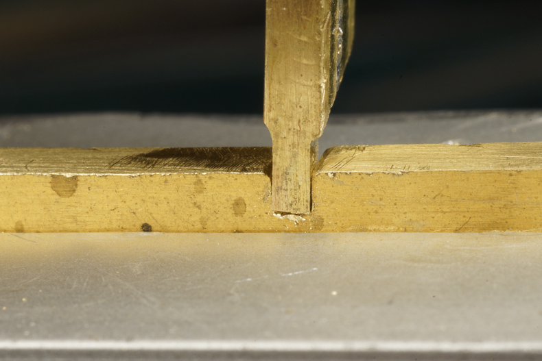
 Now lay a wire on the slot
 Push the steel in, drawing the wire with it. Gently tap it with a nylon hammer (or a piece of wood, not a heavy steel hammer).
 Done! Exactly to size and with nice crisp corners.
 Fits perfectly
 Not much to it actually. Drill a hole, solder 0.5 mm bras rod, and solder it on the other end as well.


 After soldering the handgrips where bent forward under an angle of approximately 45 degrees.
 The handgrips were soldered from the inside. Neat innit?


 A 0.4 mm hole in a 0.7 mm wide brass, hmmmm
 One done, one to go
 I soldered two pieces of brass to a sacrificial base plate. I milled them to the rectangular size (2.05 by 4.7 mm). Then I miled them down to 1.4 mm thickness and next I dropped the cutter further down by another 1.1 mm leaving the bottom end of the L-shape standing free.

 And soldered in place. Quite happy with the result although the plate looks a bit on the high side.
 LTM 51 in the cutting near Gulpen
Sign my
GuestBook